Search
communications
Cascaded Offset Optical Modulator
A unique challenge in the development of a deep space optical SDR transmitter is the optimization of the ER. For a Mars to Earth optical link, an ER of greater than 33 dB may be necessary. A high ER, however, can be difficult to achieve at the low Pulse Position Modulation (PPM) orders and narrow slot widths required for high data rates. The Cascaded Offset Optical Modulator architecture addresses this difficulty by reducing the width of the PPM pulse within the optical modulation subsystem, which relieves the SDR of the high signal quality requirements imposed by the use of an MZM. With the addition of a second MZM and a variable time delay, all of the non-idealities in the electrical signal can be compensated by slightly offsetting the modulation of the laser. The pulse output is only at maximum intensity during the overlap of the two MZMs. The width of the output pulse is effectively reduced by the offset between MZMs. Measurement and analysis of the system displayed, for a 1 nanosecond pulse width, extinction ratios of of 32.5 dB, 39.1 dB, 41.6 dB, 43.3 dB, 45.8 dB, and 48.2 dB for PPM orders of 4, 16, 32, 64, 128, and 256, respectively. This approach is not limited to deep space optical communications, but can be applied to any optical transmission system that requires high fidelity binary pulses without a complex component. The system could be used as a drop-in upgrade to many existing optical transmitters, not only in free space, but also in fiber. The system could also be implemented in different ways. With an increase in ER, the engineer has the choice of using the excess ER for channel capacity, or simplifying other parts of the system. The extra ER could be traded for reduced laser power, elimination of optical amplifiers, or decreased system complexity and efficiency.
communications
Fine-pointing Optical Communication System Using Laser Arrays
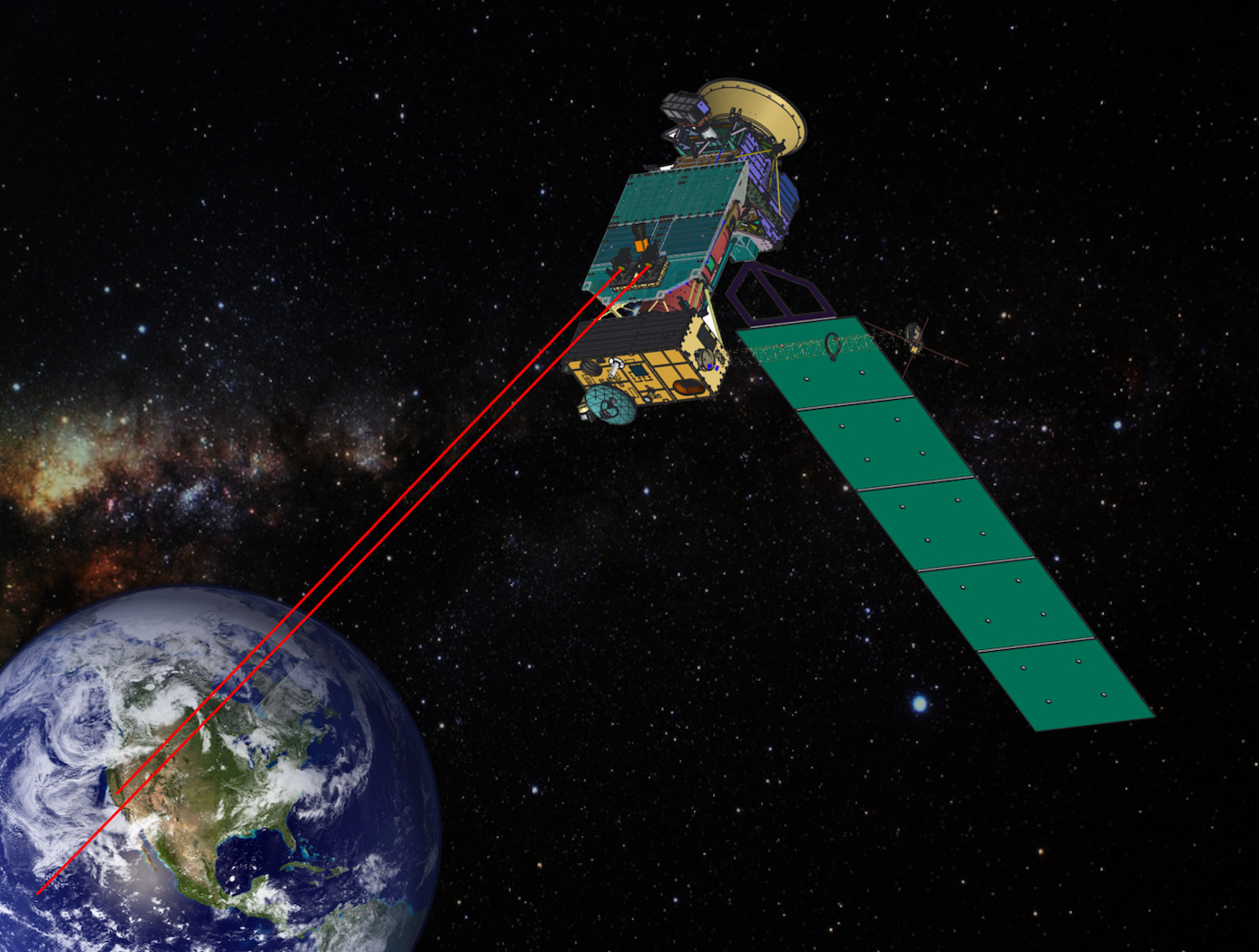
A new method is described for optical data transmissions from satellites using laser arrays for fine pointing of laser beams that use body pointing. It combines a small lens system and a VCSEL/Photodetector Array in a novel way to provide a fine pointing capability for laser beams that are pointed by body pointing of a CubeSat. As Fig. 1 shows, an incoming laser beam (green or blue, with rightward arrows), transmitted from a ground terminal, enters the lens system, which directs it to an element of the pixel array (gray rectangle). Each element, or pixel, consists of a VCSEL component/photodetector pair. The photodetector detects the incoming beam, and the VCSEL component returns a modulated beam to the lens system (green or blue, with leftward arrows), which sends it to the ground terminal. As the incoming beam changes direction, e.g., from the blue to the green incoming direction, this change is detected by the adjacent photodetector, and the laser paired with that photodetector is turned on to keep the outgoing laser beam on target. The laser beams overlap so that the returning beam continues to point at the ground terminal. The VCSEL component may consist of a single VCSEL or a cluster of VCSELs. Figure 2 shows the propagation of two overlapping laser beams. The system can very accurately point finely focused diffraction-limited laser beams. Also, simultaneous optical multiple access (OMA) is possible from different transceivers within the area covered by the laser array. For this electro-optical system, reaction times to pointing changes and vibrations are on the nanosecond time scale, much faster than mechanical fine pointing systems.
Communications

Optical Transceiver Method of QKD Encryption Suite of Technologies
The core of the technology is the SAW division de-multiplexing method (LEW-19920-1). It uses a commercially available double-clad fiber optic cable with a 9um core and a 105um first cladding. By optimizing the wavelengths of the QKD photon and data transmission, a single focusing lens can create a diffraction pattern that directs the QKD photons to the 9um core and the data signal to the 105um secondary core.
Key components of the system include:
• SOA Driver With Wideband Current Control (LEW-19913-1): This device allows a semiconductor optical amplifier (SOA) or laser to be driven with an arbitrary current at a rate of over 100 MHz. This enables the rapid generation of sub-nanosecond laser pulses with one of four polarization states, which is necessary for QKD.
• Random Bit Generator with Linear Feedback Shift Register LFSR Scrambler (LEW-20058-1): This device produces random bits by combining the output of a noise source with a pseudorandom bitstream from the LFSR. This allows a random basis set to be generated on demand for a polarization modulator.
• Variable-length quantum key conversion (LEW-20224-1): Since QKD operations produce keys of varying lengths, a strategy was developed to "digest" these raw keys using a hash function, such as SHAKE256. This process generates a fixed-length output that is useful for symmetric encryption schemes like AES256.
• The system also incorporates a Discretization Algorithm for Numerical Wave Optics Simulations (LEW-20119-1), which can accurately model the effects of atmospheric turbulence on the propagating optical beam.

